説明
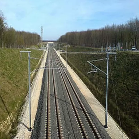
This is a formula used to minimize the number of substations to feed the line. The substation (1) transforms the power from the HV-B network (2) and feeds the catenary (3) and an overhead feeder cable called feeder (5) which are in phase opposition, each at a potential of 25 kV with respect to the rail (4), i.e. a potential difference of 50 kV between the catenary and the feeder. Diagram of a 2 × 25 kV power supply. At regular intervals, an autotransformer (9) connects the rail (10), the feeder (5) and the catenary (8) to supply the train (7) with 25 kV. The result of this arrangement is that the electrical power is then carried for a large part of the route - between the substation and the autotransformer - at 50 kV (between the feeder and the catenary), while the autotransformer delivers the power to the train at 25 kV (between the catenary and the rail). On the other hand, the current that feeds the train comes from the two autotransformers that flank it (in front and behind it), which divides the current in a catenary section. The French high-speed lines and most of the newly electrified lines in France are based on this principle. on the running track, in line with the supports, the values are, except in special cases, 5.08 m on high-speed lines and 5.50 m on other tracks The friction of the bow on the contact wire generates a mechanical wave that propagates on both sides of the contact point. For a normal tension of the contact wire, this wave propagates at less than…
About this model
LGV catenary package in N is a 無料 3D model in the 動物・クリーチャー category, shared by the Cults3D community. You can download it for 3D printing and reuse it in your own projects under the terms of its original license.
File formats
- STL — The most common mesh format for 3D printing — ready to slice and print on almost any printer.
The files for this model are hosted on Cults3D. Use the button above to open the original page and download it.